
A series current measurement introduces a voltage drop through the meter and its connections. This burden voltage can reduce the voltage reaching a battery-powered circuit, changing the very current you are trying to measure. Use the specified range characteristics and record the circuit’s operating conditions. A smaller current reading is not automatically a more accurate account of undisturbed operation.
The measurement becomes part of the circuit
A current range commonly measures the voltage developed across an internal sensing resistance. Leads, contacts, fuses and protection can add to the total series drop. The effective burden may vary with range and instrument design; do not assume a single resistance covers every mode. HKJ’s test-method page [1] discusses burden at stated currents and how it relates to the range.
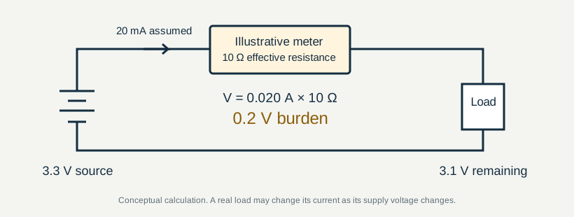
For an illustrative 10 Ω effective series resistance carrying 20 mA, V = IR gives 0.2 V drop. An ideal 3.3 V source would then leave 3.1 V across the load, ignoring other drops. This is not a tested meter specification.
Why the measured current can change
OpenStax’s discussion of meter loading [2] explains why an ammeter’s series resistance changes a circuit. The following are possible load responses, not observations of a tested device. A resistive load, a regulated converter and a microcontroller near its brownout threshold respond differently to a supply change. Some devices draw less current; some regulated loads may draw more input current to maintain power; some reset or change state. The simple voltage-drop calculation does not predict all of these behaviours.
Auto-ranging may also change the effective measuring circuit. A display that settles after a range change can hide a disturbance that already altered the device’s state. Record the range and any observed state change, rather than comparing numbers alone.
The goal is to understand the full measurement arrangement. This guide concerns current-limited low-voltage DC bench work, not direct insertion of a current range into mains wiring or high-energy battery systems.
What to record with a current result
| Record | Why it matters |
|---|---|
| Device state and timing | Startup, idle and transmission are different operating conditions |
| Supply and load-terminal voltage | Shows whether the instrument changed the available voltage |
| Current range and leads | Range changes and connections affect burden |
| Observation interval | A slow average may omit brief current peaks |
| Reference method | Reference loading, bandwidth and uncertainty also matter |
HKJ’s test-method reference [1] is a useful starting point for interpreting instrument tests. Specifications and calibration evidence should describe the exact function and conditions; agreement between two instruments does not remove either instrument’s loading.
Shunts and amplifiers have trade-offs too
A smaller shunt resistance reduces voltage drop but also reduces the signal available to the measuring system. Offset, noise and thermal effects can then become more significant. A current amplifier can help with small signals but has its own gain, offset, range and bandwidth limits.
A clamp avoids inserting a series meter, but low-current resolution and drift may limit its usefulness. The right comparison is between complete methods at the required current, time resolution and acceptable disturbance—not between headline digit counts.
Never assume a current input is suitable for direct connection across a source. Use the instrument instructions and a setup appropriate to the available energy. Our blank record template is for documenting a considered setup; it is not a wiring procedure.
Sources & scope
Sources checked on 22 September 2026. Numbered references above point to the original publishers below. Their sample measurements are not Meter & Probe measurements; manufacturer material is identified separately.
- HKJ — How digital multimeters are tested ↗Independent test methodology
- OpenStax — College Physics 2e, 21.4 DC Voltmeters and Ammeters ↗Physics textbook; explains circuit loading, not a product test
No product in this guide has been bench-tested or certified by this publication. Evidence policy · Corrections
Keep the conditions with the reading.
Use the blank CSV to record the instrument, range, reference, environment and result.
Download measurement record ↓